Home › Unlabelled ›
Phasor Diagram Of Rl Circuit - Phasor Diagram An Overview Sciencedirect Topics / When in position 1, the battery, resistor, and inductor are in series and capacitors in ac circuits:
Phasor Diagram Of Rl Circuit - Phasor Diagram An Overview Sciencedirect Topics / When in position 1, the battery, resistor, and inductor are in series and capacitors in ac circuits:. Always wanted to learn about ac. 1.phasor diagram of series rl circuit: Find the current in the circuit at any time t. In an rl series circuit the current lags behind the voltage by an angle q , this is due to the effect of inductance l. The phasor diagram for a series rl circuit shows that the total current wave lags behind the total voltage wave.
In case of series rl circuit, resistor and inductor are connected in series, so current flowing in both the elements are same i.e ir = il = i. The power factor which is the (vl leads i by 90° i.e ab represented by the phasor diagram). The resulting v(t) plots and phasor diagram look like this. So, take current phasor as reference and draw it on horizontal axis. If you think someone is going to spend time drawing a phasor diagram where r, l, c and f are all variable, think again.
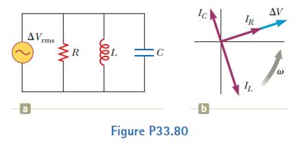
P33 80a Shows A Parallel Rlc Circuit The Instantaneous Voltages And Rms Voltages Across Each Of The Three Circuit Elements Are The Same And Each Is In Phase With The Current In The from content.bartleby.com Figure 2 parallel rl circuit vector (phasor) diagram. In case of series rl circuit, resistor and inductor are connected in series, so current flowing in both the elements are same i.e ir = il = i. In this video, phasor diagram representation of voltage and current for series rc, rl and rlc circuit has been explained and the. Phasor diagram of series rlc circuit. Phasor diagram of parallel rl circuit topics discussed: Move the sliders to change component values. In an rl series circuit, the voltage across the inductor is aheadof the current by 90°, and the inductive reactance, as we saw before, is xl = ωl. Rl circuit are commonly used in as passive filters, a first order rl circuit with only one inductor and one capacitor is shown below.
We have a circuit in the picture below.
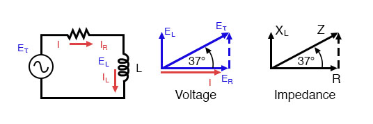
The rl circuit (resistor inductor circuit) will consist of an inductor and a resistor again connected either in series or parallel. 25 ac circuits phasor diagrams. A source delivers power to a load, represented by impedance zl = rl + j xl. Since we use phasor analysis when working with ac circuits, we can construct an expression in terms of phasor voltage and current which gives p(t) as14. Phasor diagram of a sinusoidal waveform. And this leading angle depends upon the value of inductive reactance (xl) and resistance. In an rl series circuit, the voltage across the inductor is aheadof the current by 90°, and the inductive reactance, as we saw before, is xl = ωl. Phasor diagram of series rl circuit topics discussed: Phasor and the phasor diagram in ac circuits explained. As we know that there is no pure inductance physical circuit because every coil has some winding resistance along with. In this video, phasor diagram representation of voltage and current for series rc, rl and rlc circuit has been explained and the. (1) generation, transmission, consumption of electric energy occur under sinusoidal conditions. How to solve diode circuit problems in series and parallel using ohm's law and kvl.
As we know that there is no pure inductance physical circuit because every coil has some winding resistance along with. In an rl series circuit, the voltage across the inductor is aheadof the current by 90°, and the inductive reactance, as we saw before, is xl = ωl. In an rl series circuit the current lags behind the voltage by an angle q , this is due to the effect of inductance l. So, take current phasor as reference and draw it on horizontal axis. Phasor diagram for lrc circuit.
Series Resistor Inductor Circuits Reactance And Impedance Inductive Electronics Textbook from www.allaboutcircuits.com Capacitive reactance and phasor diagrams. image to be added soon. In this video, phasor diagram representation of voltage and current for series rc, rl and rlc circuit has been explained and the. Phasor diagram of parallel rl circuit topics discussed: Rl circuit for drawing the phasor diagram of series rl circuit; If you think someone is going to spend time drawing a phasor diagram where r, l, c and f are all variable, think again. Phasor diagram of series rl circuit. It is straightforward to use pythagoras' law to obtain the series impedance and trigonometry to obtain the.
It is an electric circuit that comprises passive components of resistors and inductors if we look at the phasor diagram below.
Whether it's to pass that big test, qualify for that big promotion or even master that cooking technique; We have a circuit in the picture below. (1) generation, transmission, consumption of electric energy occur under sinusoidal conditions. The phasor diagram for a series rl circuit shows that the total current wave lags behind the total voltage wave. Taking current as references phasor, applied voltage v is the phasor sum of these two. 1) definition of phasor diagram. The phasor diagram shows the phase difference between voltage an current. Phasor and the phasor diagram in ac circuits explained. As we know that there is no pure inductance physical circuit because every coil has some winding resistance along with. This is shown in the phasor diagram of fig. Phasor diagram of series rl circuit. 1) phasor diagram of parallel rl circuit. Phasor diagram of series rl circuit topics discussed:
How to solve diode circuit problems in series and parallel using ohm's law and kvl. 1) definition of phasor diagram. In an rl series circuit, the voltage across the inductor is aheadof the current by 90°, and the inductive reactance, as we saw before, is xl = ωl. Whether it's to pass that big test, qualify for that big promotion or even master that cooking technique; Taking current as references phasor, applied voltage v is the phasor sum of these two.
Solved V Figure 7 7 Phasor Diagrams Of Series R C Circu Chegg Com from d2vlcm61l7u1fs.cloudfront.net 1) phasor diagram of parallel rl circuit. In case of series rl circuit, resistor and inductor are connected in series, so current flowing in both the elements are same i.e ir = il = i. Phasor and the phasor diagram in ac circuits explained. As is the case in all parallel circuits, the current in each branch of a parallel rl circuit acts independent of the currents in the other branches. Ac circuits basics, impedance, resonant frequency, rl rc rlc lc circuit explained, physics problems. Phasor diagram of a sinusoidal waveform. The voltage across a capacitor lags the current. If you think someone is going to spend time drawing a phasor diagram where r, l, c and f are all variable, think again.
Phasor diagram of series rl circuit.
A source delivers power to a load, represented by impedance zl = rl + j xl. What will the phasor diagram look like in case: 25 ac circuits phasor diagrams. Rl circuit for drawing the phasor diagram of series rl circuit; Dummies has always stood for taking on complex concepts and making them easy to understand. The phasor diagram of a pure inductive ac circuit is given below. The power factor which is the (vl leads i by 90° i.e ab represented by the phasor diagram). Dummies helps everyone be more knowledgeable and confident in applying what they know. How to draw a phasor diagram for an inductive load to scale. (1) generation, transmission, consumption of electric energy occur under sinusoidal conditions. The resulting v(t) plots and phasor diagram look like this. Due to the phase difference. Since we use phasor analysis when working with ac circuits, we can construct an expression in terms of phasor voltage and current which gives p(t) as14.