0 10V Dimming Wiring Diagram - 0 10v Dimming Ballast Wiring Diagram Download | Wiring ... : See the diagram below for wiring connections.. Df10p line art with dimensions. 10 appendix 10.1 inrush currents and maximum number of ecgs with circuit breakers (b characteristics), measured at un = 230 vac 10.1.1 trigger thresholds quicktronic® intelligent dali dim | new properties of qti dali. 256 levels of grey scales , soft & smoothly without any flash. The following diagram is representative of this circuit. Output constant current level can be adjusted through the control input by connecting a resistance or 0 ~ 10vdc or 10v pwm signal between dim+ and dim
A wiring diagram is a simplified standard photographic depiction of an electric circuit. The following diagram is representative of this circuit. Led pendant, sconce, or ceiling. Dimming with on/off control via relay. 0 10v dimming wiring diagram 0 10v dimmer switch leviton ip710 lfz.
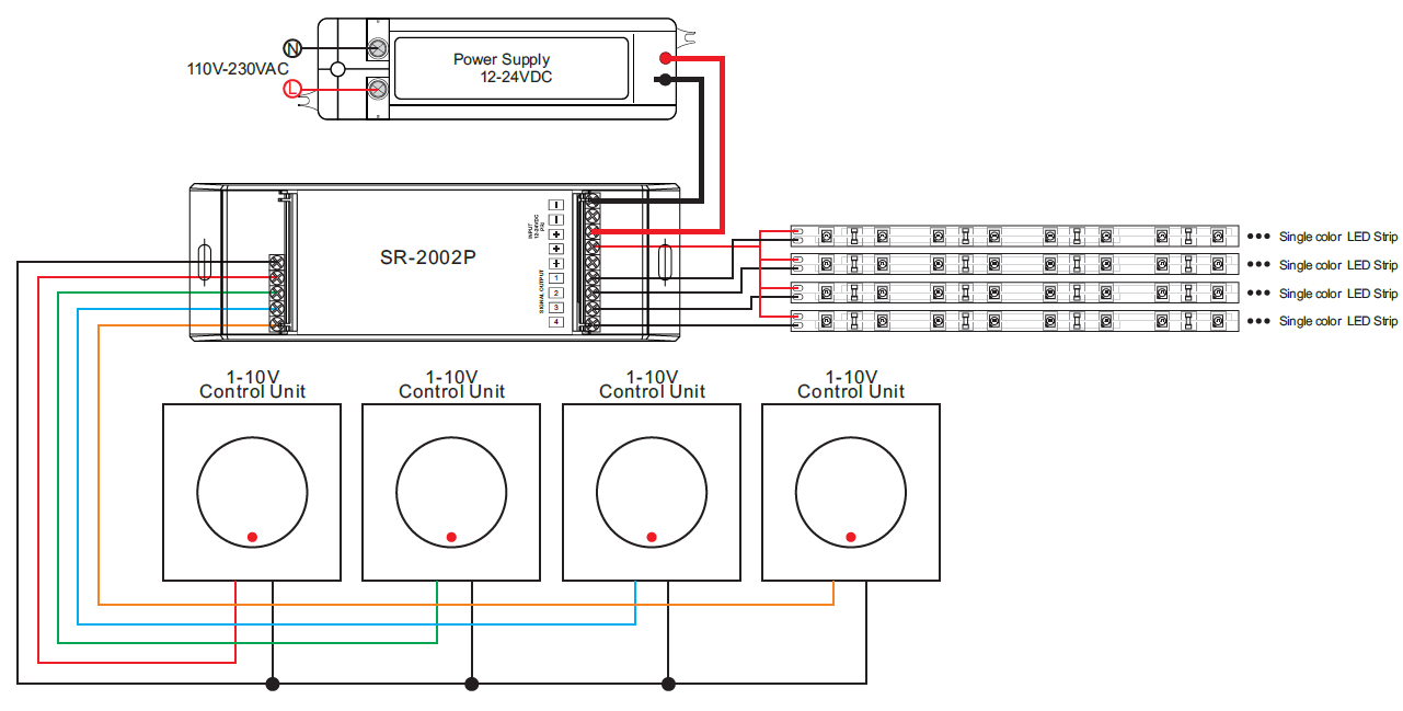
0 10v Dimming Ballast Wiring Diagram | Free Wiring Diagram from ricardolevinsmorales.com Output constant current level can be adjusted through the control input by connecting a resistance or 0 ~ 10vdc or 10v pwm signal between dim+ and dim Lutron 0 10v dimmer wiring diagram lutron 0 10v dimmer wiring diagram lutron diva dvstv v dimmer for fluorescent and led the lutron diva dvstv is a v dimmer that easily lutron dvstv v installation instructions. Osram dali ecg wiring diagram for touch dim function. Many of the led power supplies such as those by mean well, etc., offer three modes of control: Connecting coupling relays for higher load. We already described how to wire a basic inline led dimmer and a wired led controller above. Wiring example for a single dimmed light circuit. Hot (black typical) 120v or 277v, 60 hz.
See the diagram below for wiring connections.
For other types of dimming control systems, consult controls. So im assuming the pull down resistor would parallel the driver in your diagram? 10 appendix 10.1 inrush currents and maximum number of ecgs with circuit breakers (b characteristics), measured at un = 230 vac 10.1.1 trigger thresholds quicktronic® intelligent dali dim | new properties of qti dali. They are widely used with various of capacity dimming system to control the led ceiling lights, led downlights, led panel lights, led wallwashers, led strip lights and so on. Connect the control as shown in figure c2. Which one is right for you? Store 16 scene preset levels for each load. Output constant current level can be adjusted through the control input by connecting a resistance or 0 ~ 10vdc or 10v pwm signal between dim+ and dim There are two recognized standards current sourcing, and current sinking. Open dimming circuit is full brightness and 10v dimming reference is fully. There is a lot to understand and this video explains most of it. Osram dali ecg wiring diagram for touch dim function. 256 levels of grey scales , soft & smoothly without any flash.
Connect the control as shown in figure c2. A sink type dimmer is required. Refer to the wiring sheet included with the relay for more information. Which one is right for you? 10 appendix 10.1 inrush currents and maximum number of ecgs with circuit breakers (b characteristics), measured at un = 230 vac 10.1.1 trigger thresholds quicktronic® intelligent dali dim | new properties of qti dali.
Easy Connection 0/1-10V Constant Current Dimmer SR-2014P from www.sunricher.com Bu pin'i ve daha fazlasını nedim ime tarafından oluşturulan aydinlatma & veyoz panosunda bulabilirsiniz. Refer to the wiring sheet included with the relay for more information. Open dimming circuit is full brightness and 10v dimming reference is fully. Wire controls according to the appropriate wiring diagram shown in. Plug n' go™ automatic configuration for quick installation and maximum energy efficiency. So im assuming the pull down resistor would parallel the driver in your diagram? They are widely used with various of capacity dimming system to control the led ceiling lights, led downlights, led panel lights, led wallwashers, led strip lights and so on. The wiring section of this sheet and on the ballast.
Output constant current level can be adjusted through the control input by connecting a resistance or 0 ~ 10vdc or 10v pwm signal between dim+ and dim
We already described how to wire a basic inline led dimmer and a wired led controller above. Df10p line art with dimensions. Many of the led power supplies such as those by mean well, etc., offer three modes of control: Output constant current level can be adjusted through the control input by connecting a resistance or 0 ~ 10vdc or 10v pwm signal between dim+ and dim They are widely used with various of capacity dimming system to control the led ceiling lights, led downlights, led panel lights, led wallwashers, led strip lights and so on. The following diagram is representative of this circuit. Wire controls according to the appropriate wiring diagram shown in. Refer to the wiring sheet included with the relay for more information. 0 10v dimming wiring diagram 0 10v dimmer switch leviton ip710 lfz. Wiring example for a single dimmed light circuit. 10 appendix 10.1 inrush currents and maximum number of ecgs with circuit breakers (b characteristics), measured at un = 230 vac 10.1.1 trigger thresholds quicktronic® intelligent dali dim | new properties of qti dali. Lutron 0 10v dimmer wiring diagram lutron 0 10v dimmer wiring diagram lutron diva dvstv v dimmer for fluorescent and led the lutron diva dvstv is a v dimmer that easily lutron dvstv v installation instructions. The wiring section of this sheet and on the ballast.
0 10v dimming wiring diagram 0 10v dimmer switch leviton ip710 lfz. Connect the control as shown in figure c2. Hot (black typical) 120v or 277v, 60 hz. The following diagram is representative of this circuit. Simply put, the control signal is a dc voltage that varies between zero and ten volts.
0 10v Dimming Ballast Wiring Diagram | Free Wiring Diagram from ricardolevinsmorales.com They are widely used with various of capacity dimming system to control the led ceiling lights, led downlights, led panel lights, led wallwashers, led strip lights and so on. Osram dali ecg wiring diagram for touch dim function. Output constant current level can be adjusted through the control input by connecting a resistance or 0 ~ 10vdc or 10v pwm signal between dim+ and dim Refer to the wiring sheet included with the relay for more information. Many of the led power supplies such as those by mean well, etc., offer three modes of control: There are two recognized standards current sourcing, and current sinking. Plug n' go™ automatic configuration for quick installation and maximum energy efficiency. I should of gotten the eln series drivers but at the time i did'nt realise there were different types i measured the dimming terminals of the driver and it does have +10vdc across them.
256 levels of grey scales , soft & smoothly without any flash.
Dimming with on/off control via relay. The wiring section of this sheet and on the ballast. Output constant current level can be adjusted through the control input by connecting a resistance or 0 ~ 10vdc or 10v pwm signal between dim+ and dim Bu pin'i ve daha fazlasını nedim ime tarafından oluşturulan aydinlatma & veyoz panosunda bulabilirsiniz. They are widely used with various of capacity dimming system to control the led ceiling lights, led downlights, led panel lights, led wallwashers, led strip lights and so on. Store 16 scene preset levels for each load. So im assuming the pull down resistor would parallel the driver in your diagram? 10 appendix 10.1 inrush currents and maximum number of ecgs with circuit breakers (b characteristics), measured at un = 230 vac 10.1.1 trigger thresholds quicktronic® intelligent dali dim | new properties of qti dali. Refer to the wiring sheet included with the relay for more information. Connecting coupling relays for higher load. There are two recognized standards current sourcing, and current sinking. To work with power repeater to expand output. Wire controls according to the appropriate wiring diagram shown in.